
This is a self-initiated aerodynamics study: front winglets mounted either side of the front wheel of a Yamaha Tracer 900, to add downforce on the front axle for stability at speed — a question straight from the driver side of the work. Two designs were explored: a single-element wing and a split wing.
Each was modelled in Fusion 360 and run through external CFD — early studies in Autodesk CFD, final flow visualisation in Ansys Discovery. The footage below reads the flow over both designs, from front, side and angled views.
It is a complete simulation-driven design loop — hypothesis, parametric geometry, CFD, quantified result. The same physics-based method underpins my environmental wind and comfort analysis in landscape and urban design: a driver's question, answered with the landezing toolkit.
01 — Hypothesis
Front-axle load, without the bulk
A motorcycle front end sheds load — and grip — as speed climbs and lift builds. A compact winglet set, placed low and forward beside the wheel, can press the nose down where it matters.
The constraint was plain: meaningful vertical force for minimal frontal area and drag penalty. Everything after this was a search for that balance.
02 — Geometry
One wing resolved — a split wing in flow
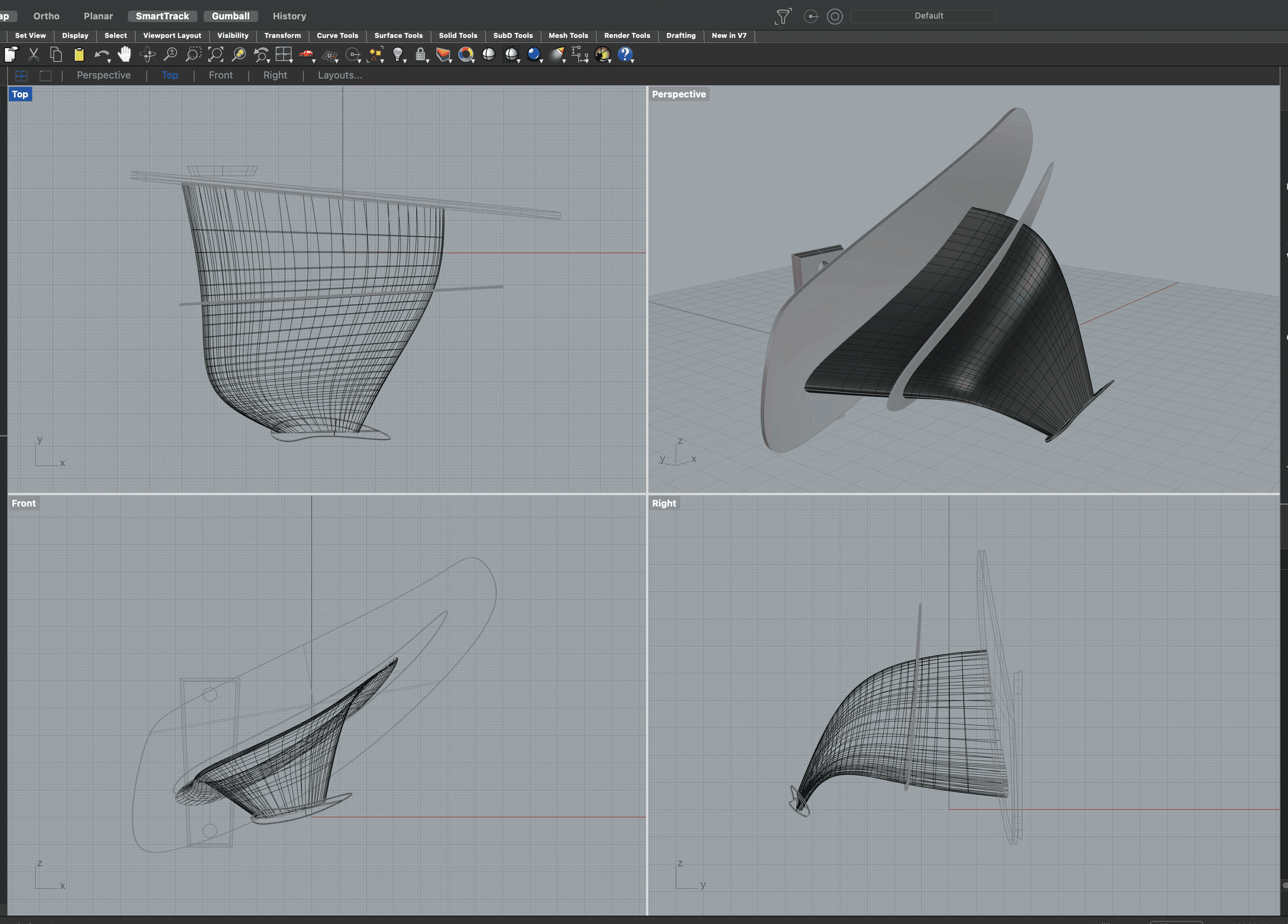
The single-element wing is the version I could model and resolve end to end — its solid, shown here, stayed parametric in Fusion 360 so each change fed straight into the next run.
A split-wing variant — two smaller elements instead of one surface — was tested too. Its solid is archived, so I read it where it counts: in the CFD footage below, against the single wing.
03 — Simulation Setup
External flow, measured at the wall
The winglets sat in an external flow domain, solved across the target speed range — up to roughly 218 km/h at the inlet. Output was read as wall results: pressure and resolved force, per surface.
Ansys Discovery drove live flow visualisation; Autodesk CFD produced the quantified force tables used to rank the design.
04 — Results
−4.8 N down, for 1.9 N of drag
At the simulated condition the winglet pair — one each side of the wheel — together produced a downforce of ≈ 4.8 N against only ≈ 1.9 N of drag, over a combined surface of 122 cm². Modest in absolute terms, but a clean proof of concept. The geometry does what it was drawn to do.
The flow tells the rest: it stays attached over the element, the wake is organised, and there is no large separated region bleeding energy.

05 — CFD Footage
The flow, frame by frame
Recorded straight from the solver — the single-element wing from the front and side, and the split-wing variant in flow and in section. This is where the two designs are actually compared.
06 — Fabricated
From solver to 3D print
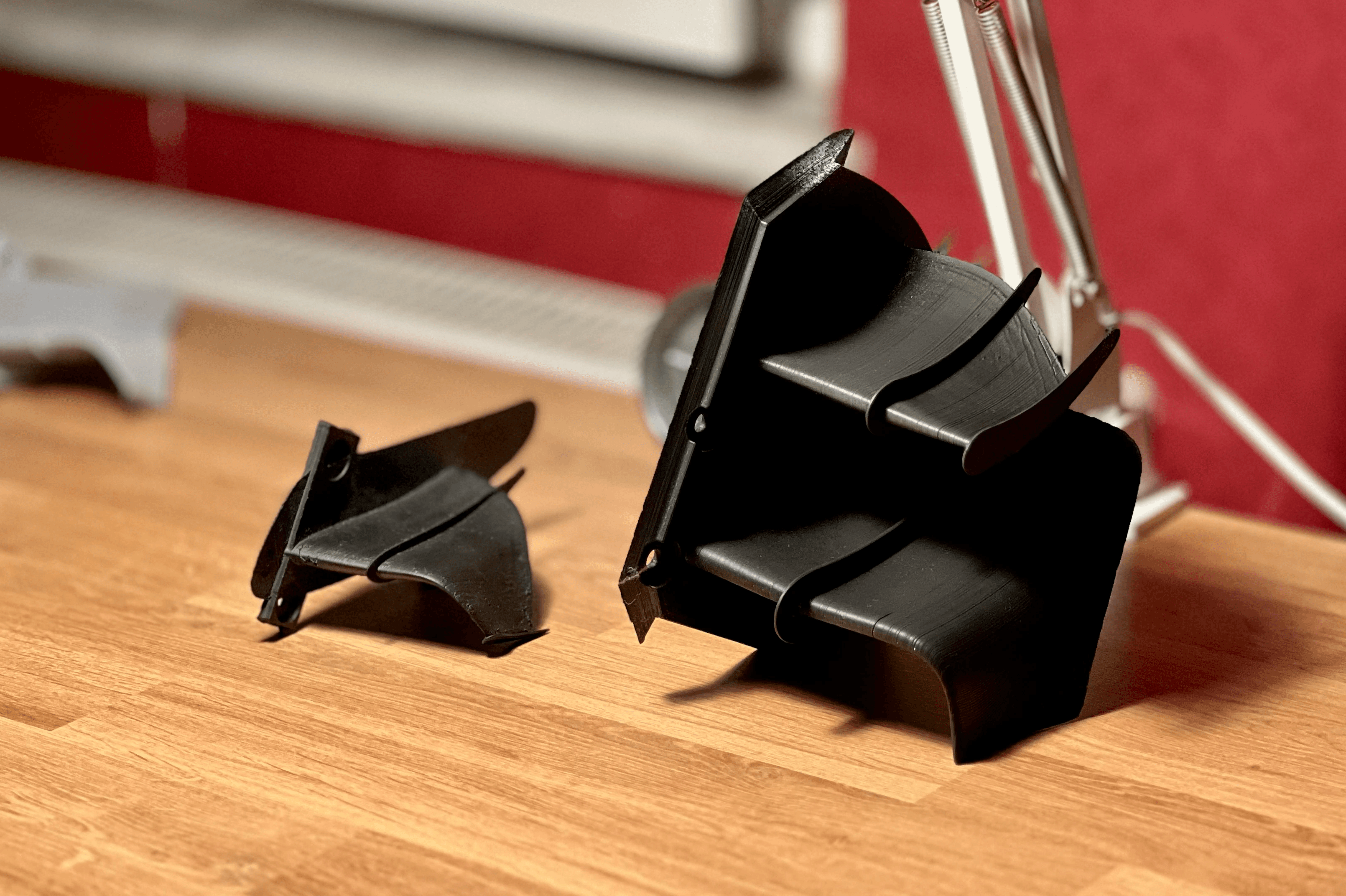
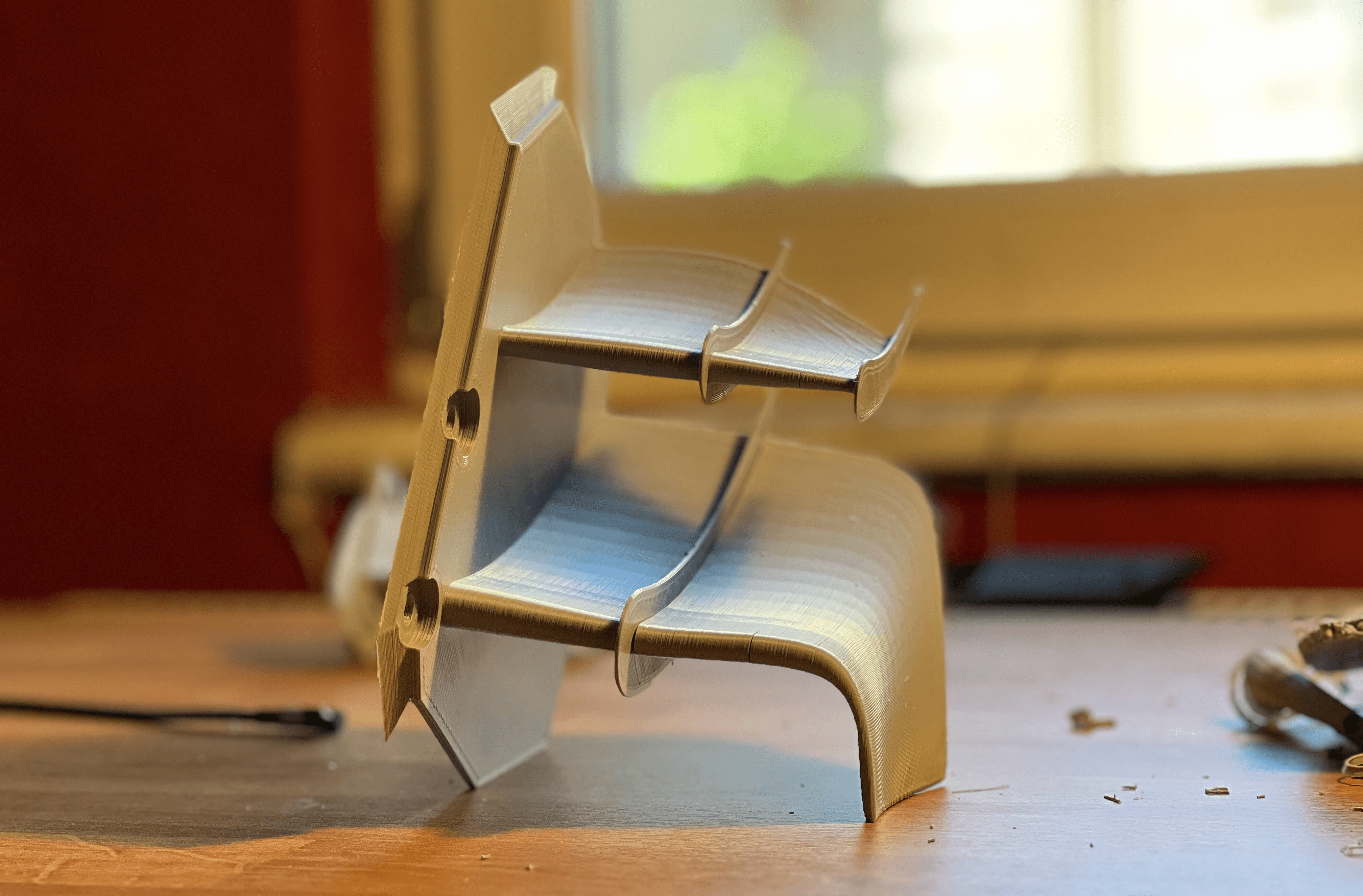
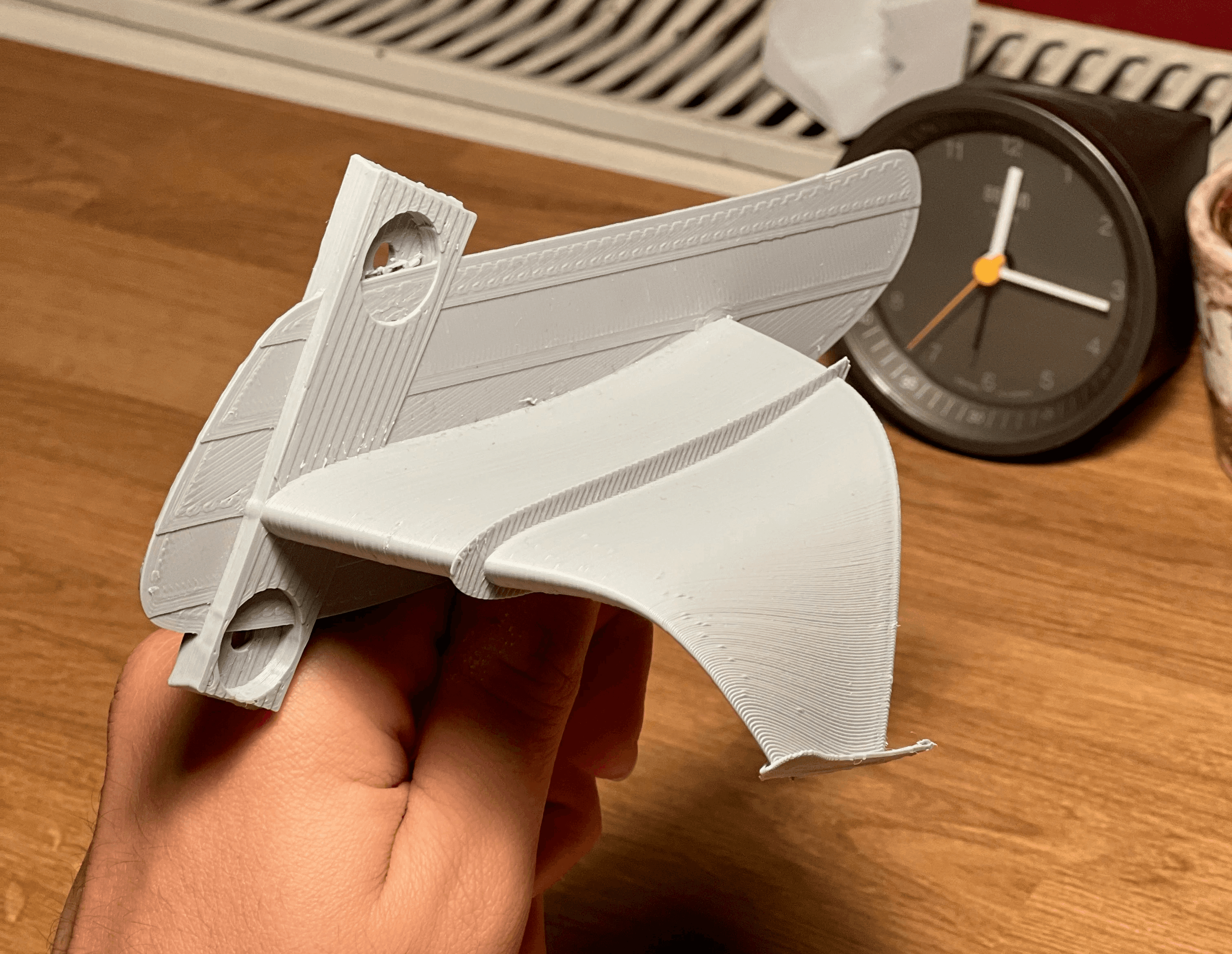
The winglets didn't stay on screen. Both the single-element and the split wing were 3D-printed in PLA and checked in the hand — chord, curvature and mounting tab, exactly as drawn.
Holding the part is its own test: the airfoil section reads clean, the wall prints without support scars, and the mount lines up with the fork. Simulation said it should work — the print said it could be made.
07 — Takeaway
The method travels both ways
A motorcycle winglet and a city plaza ask the same question: where does the air go, and what does it do to the bodies in it. This study lives on both sides of the practice — a driver's problem solved with the landezing CFD loop I bring to pedestrian wind comfort and microclimate work.